
Oscilloscope Verification of the CCi-MOBILE Platform
RF Output Validation and Channel Synchronization
To ensure that the CCi-MOBILE is working as expected in real-time, and before recuriting subjects for accuracy analysis of the platform, it is necessary to check all aspects of the generated output signals. The following experiment and its multiple sections will be justifying the desired validity of the system. This experiment will help researchers to understand the features supported by CCi-MOBILE and further motivate them to perform experiments on their own to fully exploit the potential of the platform. Outputs generated by the RF Coils and Acoustic Line-out are analyzed for synchroninzation in this experiment verifying both the bilateral and bimodal systems.
Experiment Aims
1. Left and Right channel output synchronization for-
a. Acoustic Bilateral (For hearing aids on both ears)
b. Electric Bilateral (For cochlear implants on both ears)
c. ELectric and Acoustic (EAS) Bilateral (A cochlear implant on one ear and an hearing aid on another)
2. Varying User defined MAP parameters at the input and analyzing the output
Experimental Protocol
- Two similar implant emulators (model #CI24RE from Cochlear Corporation) were used
- Sets of tones, words and sentences have been passed from the microphone through the CCi-MOBILE to validate the results
- Output at the receiver coil were verified on the oscilloscope
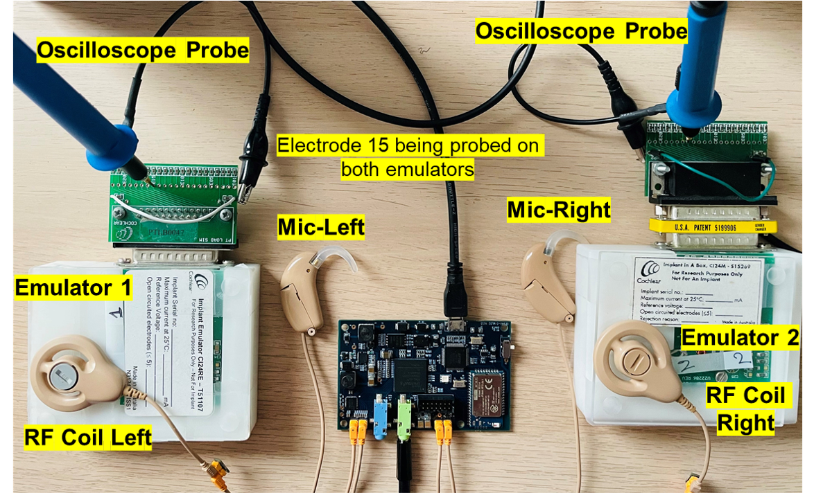
Experimental Setup
Experiment #1 – Channel synchronization Check
A. Acoutic Bilateral:
Audio was sent simultaneously through both the left and right input microphones. The incoming audio was sampled at 16KHz, processed and amplified by the on-board CODEC, sent through the FPGA and out to the Line-OUT.
The left and the Right output channels then can be monitored on an oscilloscope through a male to male Line-IN. The first oscilloscope result is the case when the source is equidistant from both left and right microphone.
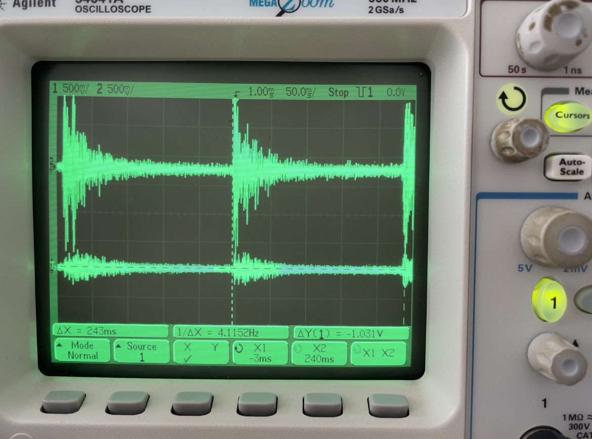
The second image highlights directional properties when the source is closer to the Left mic and from the right microphone.
A. Electric Bilateral:
Same as the previous experiment, audio was sent simulatenously to the left and right microphones and the results of electric stimulation on the RF coils were analyzed through the emulators on the oscilloscope.
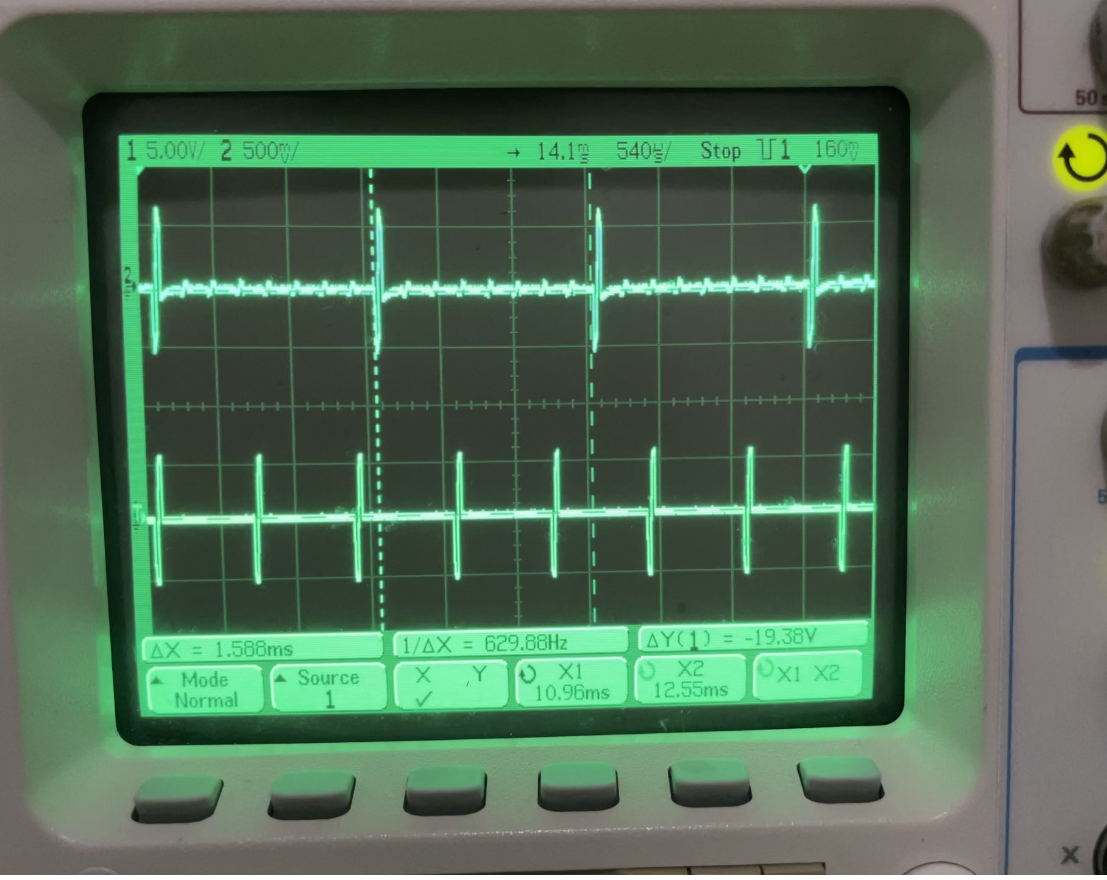
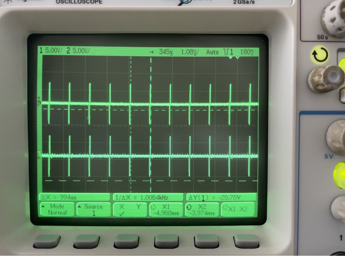
Electric stimulation are sent in the form of biphasic pulses to guarantee charge balance throughout the transmission of the signal as shown below. The distance between the pulses is defined as the stimulation rate, i.e. how often would a biphasic pulse be generated.
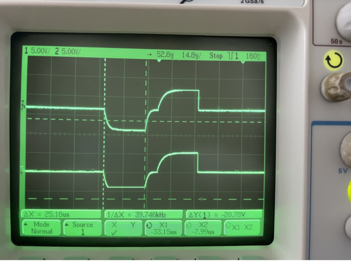
As mentioned before out, the stimulation rate is one of the many parameters that can be varied by reseachers. The stimulation rate in this experiment has been maintained at 1KHz, which can be seen as 1/ΔX in the first oscilloscope result. The second result is a fine tuned
channel synchronization analysis with the left and right biphasic pulse starting at the exact same time both having a pulse width of 25µs and no real-time delay. Electrode #15 was probed on both emulators for the RF coil results.
A. Electric and Acoustic (EAS) Bilateral:
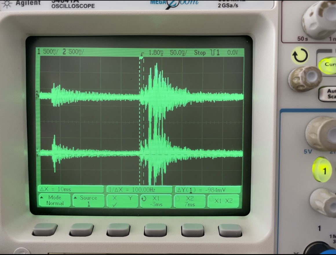
The left and right microphone received simultaneous audio, generating an electric channel output from the RF coil through the emulator and the other an acoustic output from the Line-OUt port through the Line-IN cable.
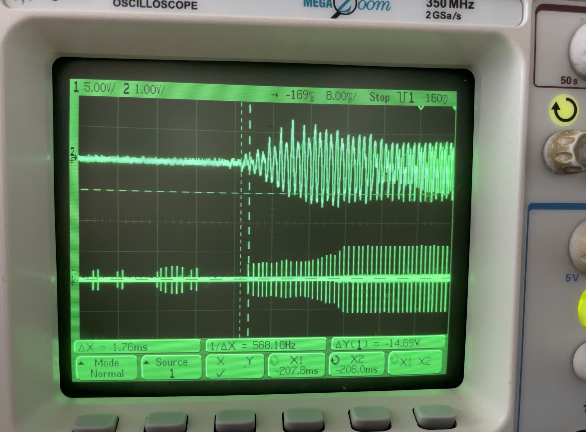
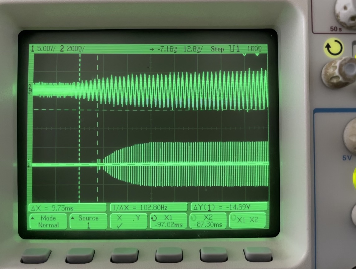
With two different forms of signals, synchronization becomes a bit difficult, but past research suggests a delay of 10ms or less does not affect the performance of speech or sound perceived by humans with hearing impairment. The first scope results is the word "Hello" being pronounced in real-time thorugh a .wav file. The above channel is the audio channel, while the bottom channel is the electric stimulation on the right channel.
As it can be seen there is a slight ΔX delay of 1.76ms, which should not affected the real-time speech perception of a bimodal subject. Further subject tests are going to be performed with the CCi-MOBILE to validate this issue. The next scope result is that of a 440Hz tone input probed on electrode 20 of the implant emulator. the ΔX delay as the oscilloscope shows is 9.73ms, which again is under 10ms, but further wrk is being done to fine tune the audio with the elctric output.
Experiment #2 – User Defined MAP parameter Check at Output
As highlighted before that CCi-MOBILE is a platform for flexible, on-the-go signal processing adjustments and to demonstrate such features an eperiment was performed to have varied values of parameters on each channel through a Sample MAP (which contains all the details about the parameters)
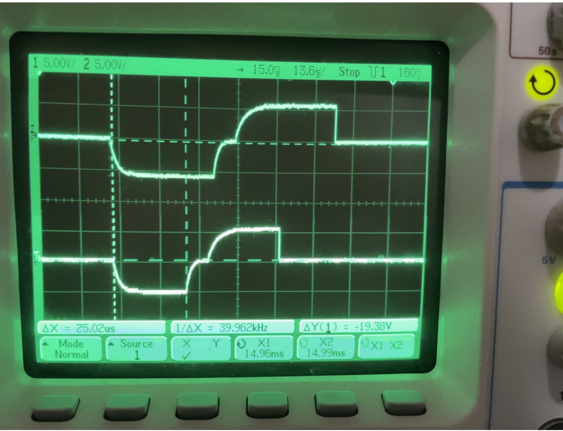
so as to compare how would be be like for researchers to change such variables while performing own custom experiments. The first result, shows different pulse-widths for the biphasic pulses in each channel. The Left channel pulses were given a 35µs input pulse width, where as the right channel was given the default 25µs pulse width.
The real-time results, can be clearly seen on the scope. The second scope result shows stimulation-rate as the varying user-defined parameter. Here the left channel is given a stimulation rate of 700Hz, while the right input channel was provided with the default of 1KHz stimulation-rate. these parameter values might not be useful during subject tst, but are mainly presented to show reseachers the effective firmware on the platform that can handle real-time signal processing.