Hardware Design: CCi-MOBILE Hardware Design and System Overview
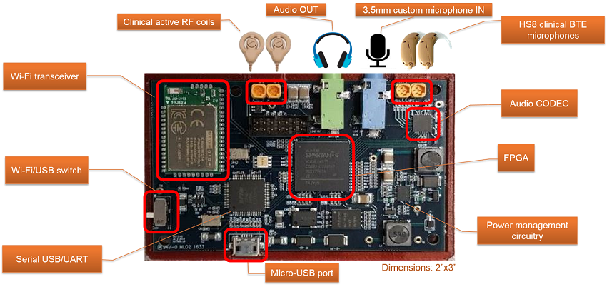
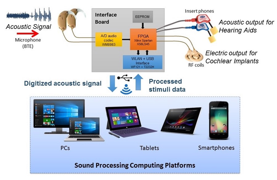
The CCi-MOBILE interface board is designed by Cochlear Implant Laboratory at UT-Dallas. It houses an FPGA, a high-quality 4-channel audio CODEC, USB interface, Wi-Fi trasceiver for wireless data exchange, audio I/O ports, connections for clinical Behind-the-Ear (BTE) microphones and RF coils. It's a very powerful and highly re-configurable platorm and comes in a very compact form factor. It is roughly the size of a credit card and is thus very portable and ideal for field evaluations. For full speficiations and componant details, please refer to the CCi-MOBILE Technical Manual.
Individual CCi-MOBILE Components
High-Level Schematic of Transmission Protocol
Verification of CCi-MOBILE: RF Output and Channel Synchronization
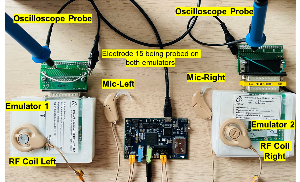
Overview: Using the experimental setup with the components from Cochlear Corp., CCi-MOBILE users can follow the protocol to verify CCi-MOBILE in their own research lab setting to ensure desired RF stimuli is recieved at the RF output. If you or your research instituion is experiencing any trouble verifying RF output, contact any of the members of our team so we can help provide a solution. The verification provided below is an updated version of the previous Verification Experiment performed in 2016.
Purpose: To ensure that CCi-MOBILE is functioning in real-time, prior to subject testing, it is necessary to check the various aspects of the generated output signals. The following set of experiments will verify the system input/output. This protocol will help researchers to understand the features supported by CCi-MOBILE and further motivate them to perform experiments on their own to fully exploit the potential of the platform. Outputs generated by the RF coils and acoustic output (line-out) are analyzed for synchroninzation in this experiment verifying both the bilateral and bimodal systems.
Experiment Aims1. Verify left/right channel synchronization for each type of processing:
o Bilateral (Acoustic-only): Hearing aids (HA) on L/R
o Bilateral (Electric-only): Cochlear implants (CI) on L/R
o Electric and Acoustic (EAS): HA on either R/L, CI on other R/L
2. Varying user-defined MAP parameters
Experimental Materials
Experiment #1: Verification of Channel Synchronization
Bilateral (Acoustic-only): Hearing aids (HA) on L/R
Overview: Audio was sent simultaneously through both the left and right input microphones. The incoming audio was sampled at 16KHz, processed and amplified by the on-board CODEC, sent through the FPGA and out to the acoustic line-out. The left and right output channels were monitored on an oscilloscope through a male to male line-in.
Results: The figure on the left represents the case where the source is equidistant from both left and right microphones. The figure on the right represents the case where the source is closer to the left microphone.
Bilateral (Electric-only): Cochlear implants (CI) on L/R
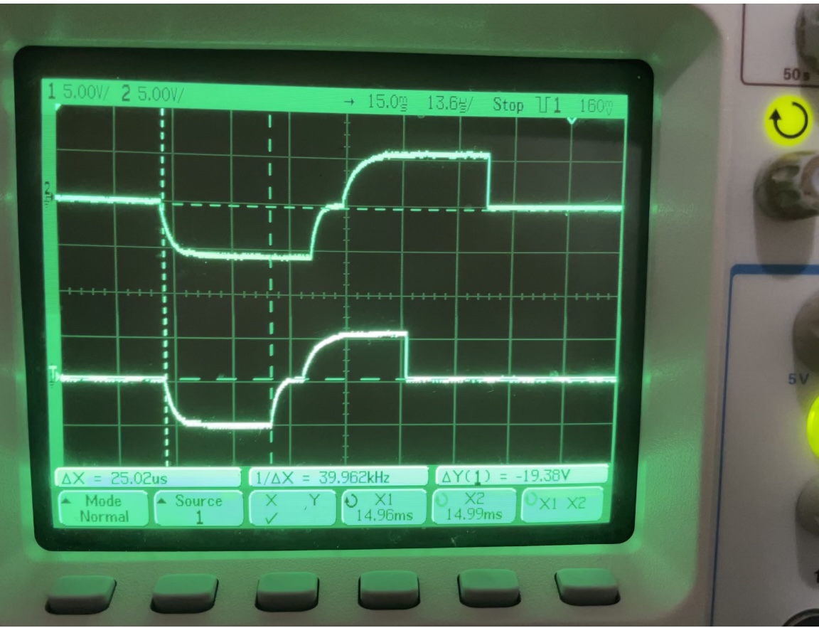
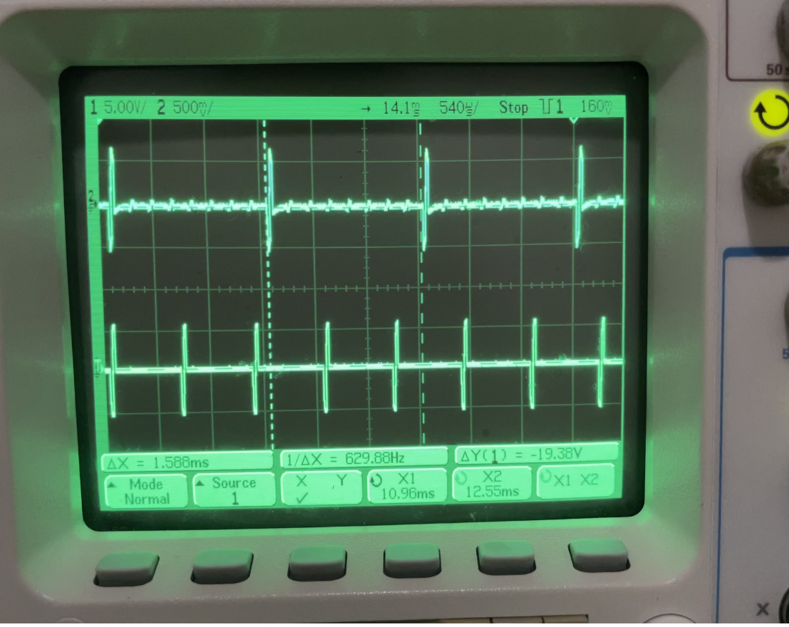
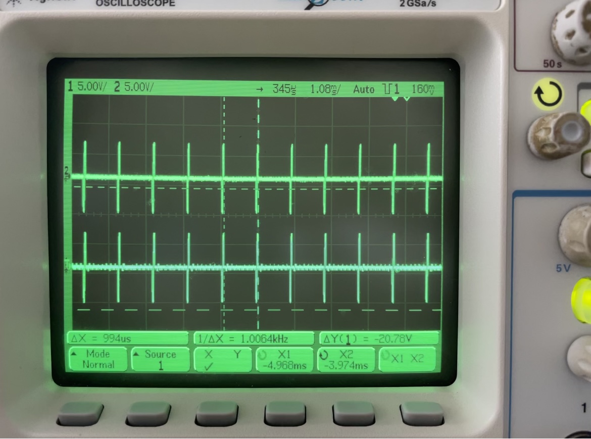
Overview: Audio was sent simulatenously to the left and right microphones and the results of electric stimulation on the RF coils were analyzed through the emulators and visualized on the oscilloscope. Electric stimulation is sent in the form of biphasic pulses to maintain charge balance throughout the transmission of the RF signals as shown below. The distance between the pulses is defined as the stimulation rate, i.e. how often would a biphasic pulse is generated per channel per second. The stimulation rate is one of the many parameters that can be varied by user. Electrode #15 was probed on both emulators for the RF coil results.
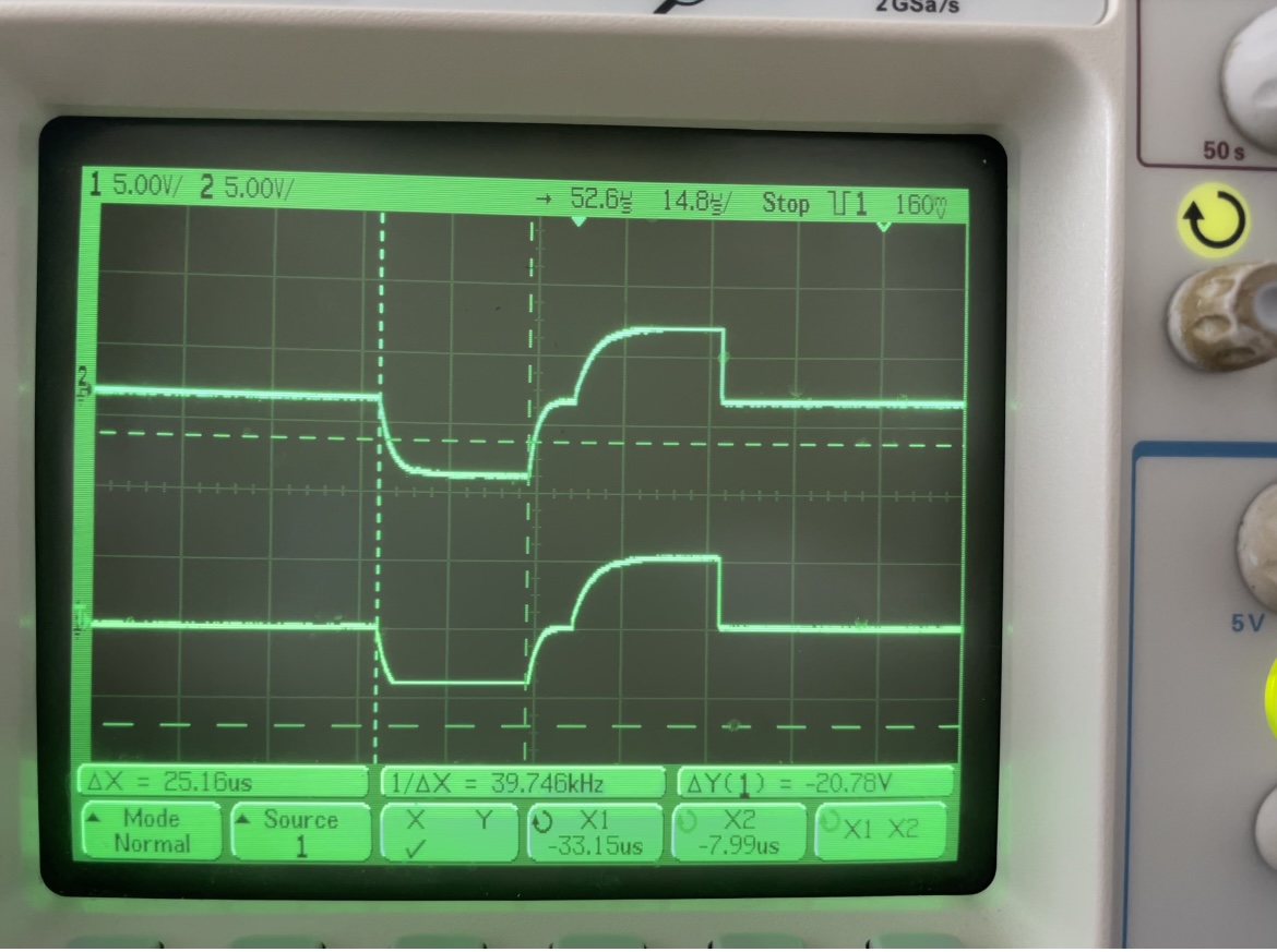
Results: The figure on the left shows a stream of biphasic pulses at a stimulation rate at 1KHz which is maintained on both channels and can be seen as 1/ΔX on the oscilloscope. The figure on the right illustrates biphasic pulses on each of the left and right channels starting at the exact same time (pulse width of 25µs) without any real-time delay.
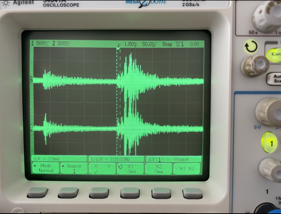
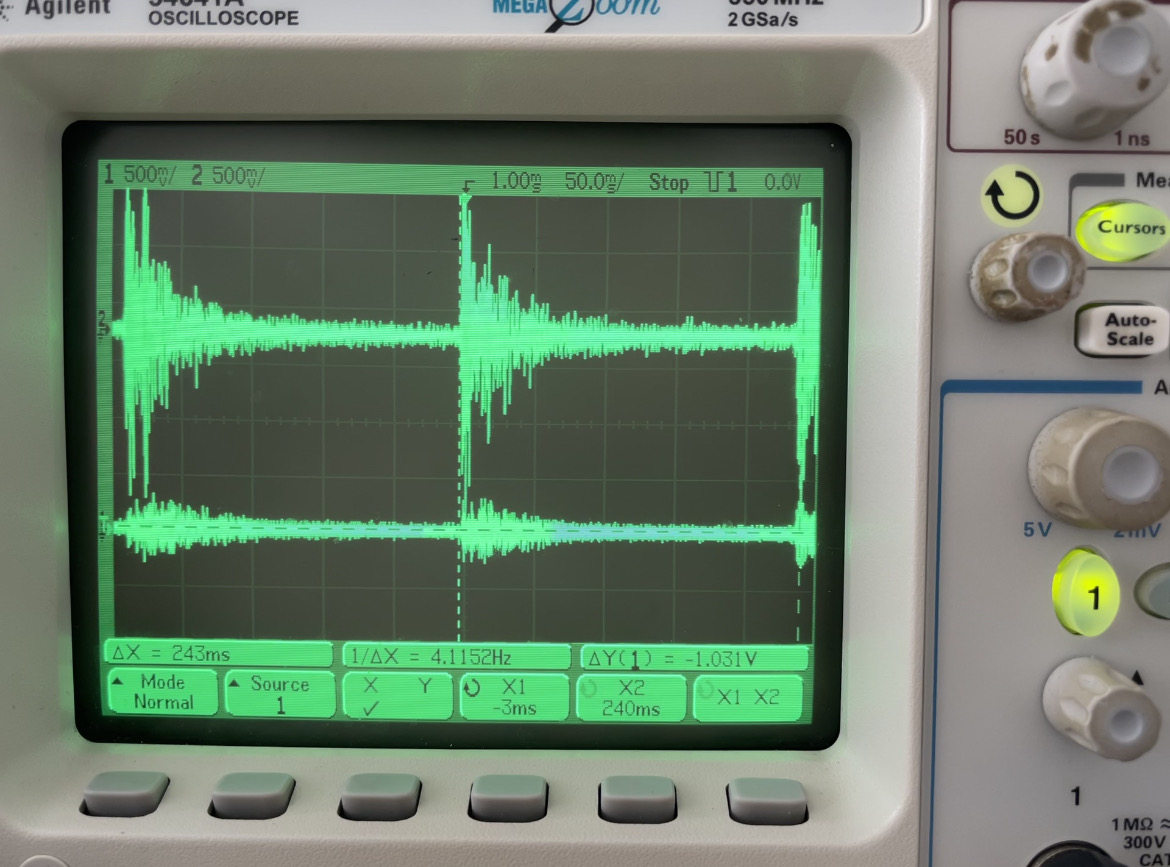
Electric and Acoustic (EAS): HA on either R/L, CI on other R/L
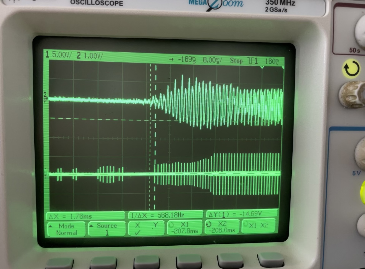
Overview: The left and right microphones receive simultaneous audio, generating an electric channel output from the RF coil through the emulator and the other an acoustic output from the line-out port through the line-in cable. It is important to note that analysis of acoustic and electric signals simultaneous on the oscilloscope is a difficult task. The word, "Hello" was spoken in real-time as the stimuli. The top channel represents the hearing aid (acoustic), whereas the bottom channel represents the cochlear implant (electric).
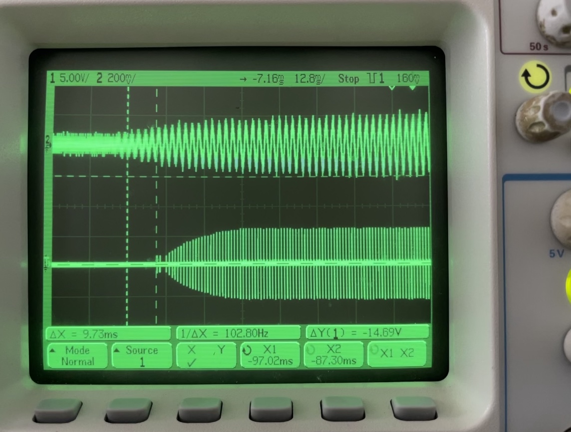
Results: The figure on the left illustrates a delay (ΔX) of 1.76ms and the figure on the right illustrates a delay (ΔX) of 9.73ms. (which is consistent within the range of values recieved from triplicate trials). Based on previous literature, delays less than 10ms should not affect hearing impaired listeners. While, larger delays may be percieved by listeners, CCi-MOBILE operates below 10ms delays.
Experiment #2: Verification of User Defined MAP Parameters
Overview: Various MAP values on each channel were verified on the oscilloscope using the sample MAP template to emulate CCi-MOBILE users flexibility in adjusting pulse width and stimulation rate (as an example).
Results: The figure on the left illustrates two different pulse-widths for the biphasic pulses in each channel. The pulse width of the left channel was 35µs (same as the input) and the pulse width of the right channel 25µs (same as the input). The figure on the right shows two different stimulation rates. Here, the left channel has a rate of 700Hz, while the right input channel was provided with the default of 1KHz stimulation-rate. The input values were verified for both cases.